Figure 1.0 Apple Bus
Figure 1.1 Card Edge Dimensions
Back
Non-ugly version of diagrams will be available as soon as I magically acquire
talent.
Apple// Internal Slot
(Hereafter referred to as the 'Apple Bus')
|
__ |
|
|
Figure 1.0 Apple Bus
|
Figure 1.1 Card Edge Dimensions |
Figure 1.1 Card Edge Dimensions
__A. 7.62 mm Card
edge depth
__B. 1.778 mm Finger width
__C. 2.54 mm Finger spacing
Table 1.0 Apple Bus Pinout Description
| Pin |
Name
|
______Description |
| 1 |
I/O SEL
|
Normally high; goes low during phase 0 when the 6502 addresses location $CnXX, where n is the connector number. This line can drive 10 LS TTL loads. |
| 2 |
A0
|
Three-state address bus. The address becomes valid during phase 1 and remains valid during phase 0. Each address line can drive 5 LS TTL loads. |
| 3 |
A1
|
|
| 4 |
A2
|
|
| 5 |
A3
|
|
| 6 |
A4
|
|
| 7 |
A5
|
|
| 8 |
A6
|
|
| 9 |
A7
|
|
| 10 |
A8
|
|
| 11 |
A9
|
|
| 12 |
A10
|
|
| 13 |
A11
|
|
| 14 |
A12
|
|
| 15 |
A13
|
|
| 16 |
A14
|
|
| 17 |
A15
|
|
| 18 |
R/W
|
Buffered read/write line. Valid at the same time as the address bus; high during a read cycle, low during a write cycle. It can drive 2 LS TTL loads. |
| 19 |
SYNC
|
Composite horizontal and vertical sync, on expansion slot 7 ONLY. This line can drive 2 LS TTL loads. |
| 20 |
I/O STR
|
Normally high; goes low during phase 0 when the 6502 addresses a location between $C800 and $CFFF. This line can drive 4 LS TTL loads. |
| 21 |
RDY
|
Input to the 6502. Pulling this line low during phase 1 halts the 6502 with the address bus holding the address of the location currently being fetched. This line has a 3300 ohm pullup resistor to +5V. |
| 22 |
DMA
|
Input to the address bus buffers. Pulling this line low during phase 1 disconnects the 6502 from the address bus. This line has a 3300 ohm pullup resistor to +5V. |
| 23 |
INT OUT
|
Interrupt priority daisy-chain output. Usually connected to pin 28. |
| 24 |
DMA OUT
|
DMA priority daisy-chain output. Usually connected to pin 22. |
| 25 |
+5V
|
+5V power supply. A total of 500mA is available for all accessory cards. |
| 26 |
GND
|
System common ground. |
| 27 |
DMA IN
|
DMA priority daisy-chain input. Usually connected to pin 24. |
| 28 |
INT IN
|
Interrupt priority daisy-chain input. Usually connected to pin 23. |
| 29 |
NMI
|
Non-maskable interrupt to 6502. Pulling this line low starts an interrupt cycle with the interrupt-handling routine at location $03FB. This line has a 3300 ohm pullupresistor to +5V. |
| 30 |
IRQ
|
Interrupt request to 6502. Pulling this line low starts an interrupt cycle only if the interrupt-disable (I) flag in the 6502 is not set. Uses the interrupt-handling routine at location $03FE. This line has a 3300 ohm pullup resistor to +5V. |
| 31 |
RES
|
Pulling this line low initiates a reset routine. |
| 32 |
INH
|
Pulling this line low during phase 1 inhibits (disables) the memory on the main circuit board. This line has a 3300 ohm pullup resistor to +5V. |
| 33 |
-12V
|
-12V power supply. A total of 200mA is available for all accessory cards. |
| 34 |
-5V
|
-5V power supply. A total of 200mA is available for all accessory cards. |
| 35 |
3.58Mhz
|
3.58MHz color reference signal, on slot 7 ONLY. This line can drive 2 LS TTL loads. |
| 36 |
7Mhz
|
System 7MHz clock. This line can drive2 LS TTL loads. |
| 37 |
Q3
|
System 2MHz asymmetrical clock. This line can drive 2 LS TTL loads. |
| 38 |
PHASE 1
|
6502 phase 1 clock. This line can drive 2 LS TTL loads. |
| 39 |
uPSYNC
|
The 6502 signals an operand fetch by driving this line high during the first read cycle of each instruction. |
| 40 |
PHASE 0
|
6502 phase 0 clock. This line can drive2 LS TTL loads. |
| 41 |
DEV SEL
|
Normally high; goes low during phase 0 then the 6502 addresses location $C0nX, where n is the connector number plus 8. This line can drive 10 LS TTL loads. |
| 42 |
D0
|
Three-state buffered bi-directional data bus. Data becomes valid during phase 0 high and remains valid until phase 0 goes low. Each data line can drive one LS TTL load. |
| 43 |
D1
|
|
| 44 |
D2
|
|
| 45 |
D3
|
|
| 46 |
D4
|
|
| 47 |
D5
|
|
| 48 |
D6
|
|
| 49 |
D7
|
|
| 50 |
+12V
|
+12V power supply. A total of 250mA is available for all accessory cards. |
___The Apple bus is a standardized¹ interface
for peripheal expansion of the Apple 2 family of personal computers.² It
consists of a fifty pin card edge connector for peripheal cards, and the associated
slot on the Apple 2 mainboard. Minor differences exist between the computers
within this family, and also between the slots on a single mainboard, depending
on position. Typical peripheal cards do not directly fit into the backplate
of the computer, as do more popular bus architectures. Connectors generally
connect to a card via a ribbon cable, and are attached to the back plate with
screws.
1. As standardized as any other expansion slot.
2. The Apple//c computer has no internal expansion slots.
Apple// Expansion Card
Max Dimensions
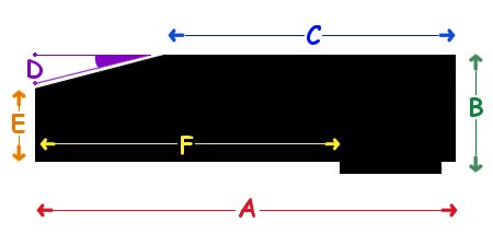
Figure 1.2 Apple// Card Max. Dimensions
Figure 1.2 Apple// Card Max. Dimensions
__A. 10.75"
Total Length
__B. 0 Height
__C. 7.75" Top Length
__D. 15° Slope Angle
__E. 2" Frontal Height
__F. 0 Frontal Length
___The Apple// series of computers
Special thanks to Wayne S., Brian V., and Aaron P. of comp.sys.apple2 !